Substations
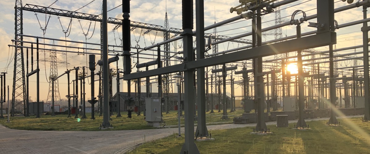
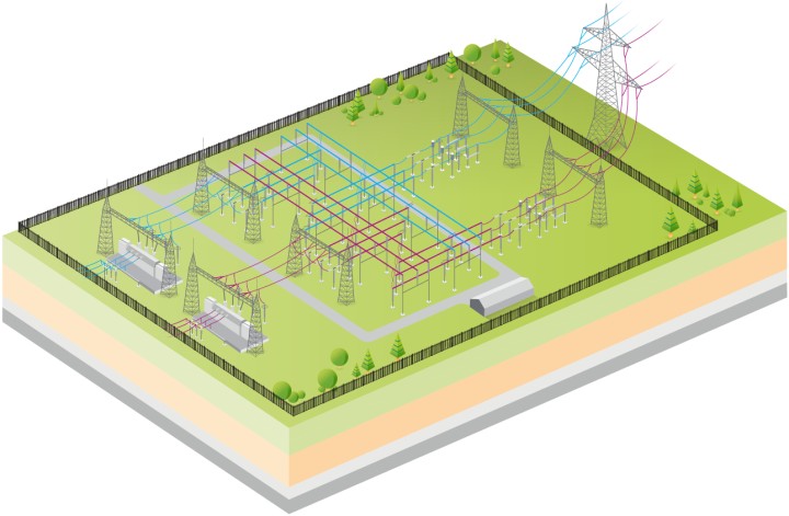
Substations and step-up stations are the hubs of our transmission network. They perform various functions that are critical to the uninterrupted operation of our transmission network. Their main tasks include switching power lines on and off and stepping up electrical energy between different voltage levels.
Did you know?
The transformers in our substations convert voltage from, for example, 380 to 220 or 110 kilovolts. Distribution system operators use this voltage to transmit the electricity further, then step-down the voltage in stages to the voltage level required by the end user, such as 230 volts. Today’s largest transformers have an electrical demand of up to 600 megavolt-amperes and weigh up to 450 tons.
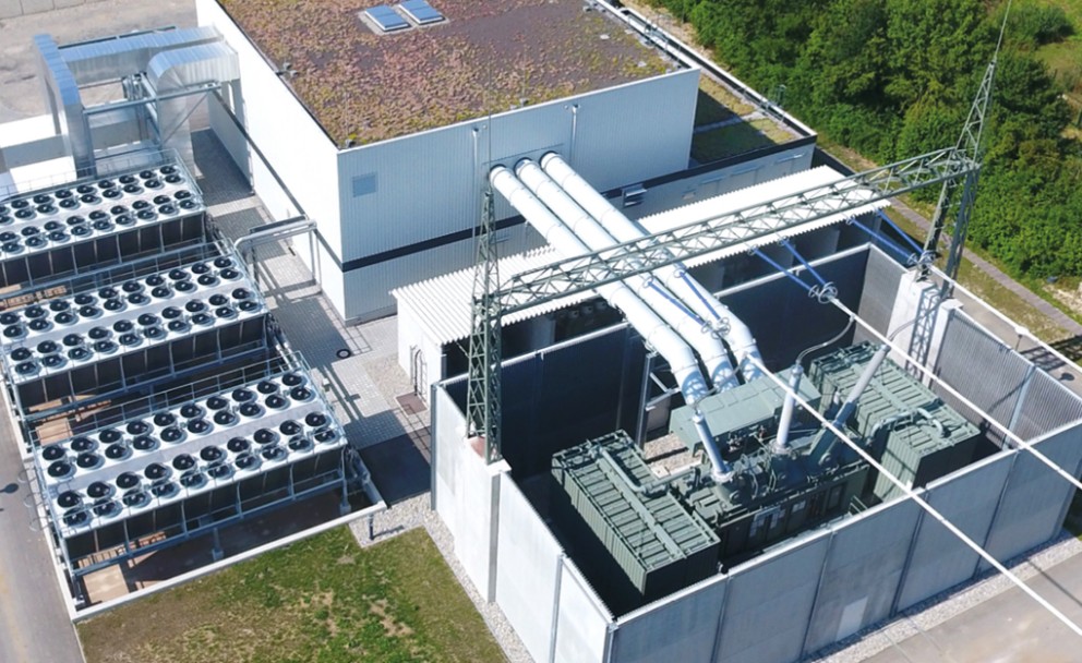
Invisible but crucial: Reactive power for stable grids
Today, our assets also perform a key function: they stabilize the mains voltage. To do this, alternating current requires reactive power—simply put, an accompanying energy that enables the constant creation and dissipation of electric and magnetic fields. This energy does not reach households and businesses as useful energy, but it places a load on the lines and reduces the amount of active power that can be transmitted.
In the past, reactors at large power stations were the primary source of reactive power. With the energy transition, many of these power stations are being taken off the grid, while demand is rising because ever-greater amounts of power are being transmitted over long distances. Amprion is therefore increasingly installing reactive power compensation systems.
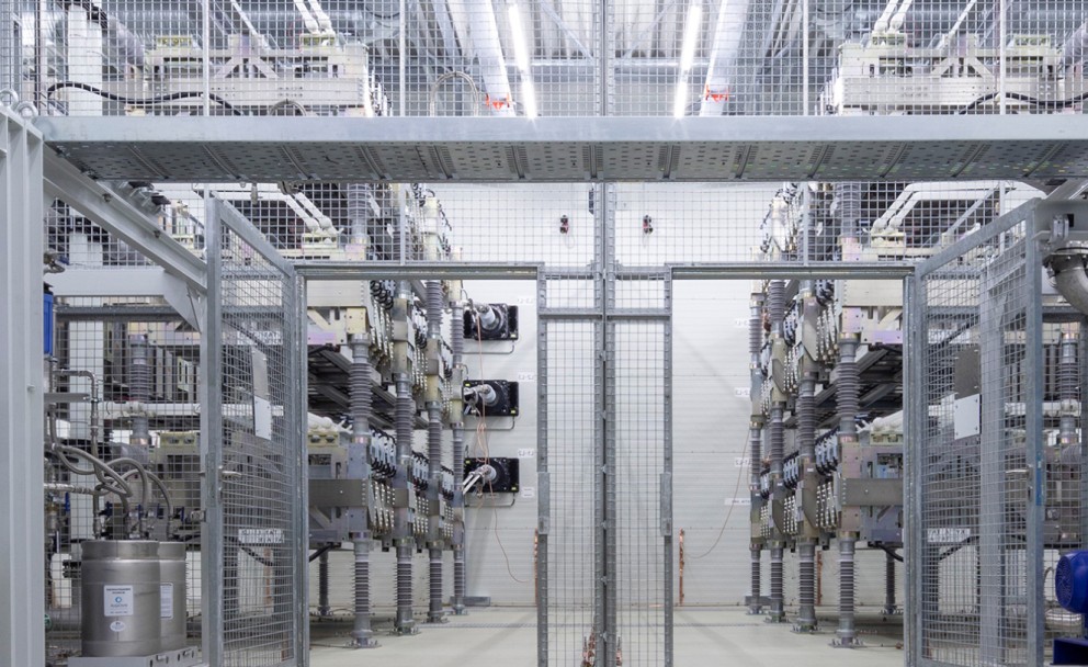
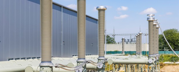
SF6 – A Safe Insulating Gas That Deserves Special Care
SF6 is the gas most commonly used in gas-insulated switchgear—a colorless, odorless gas that is non-toxic, non-flammable, and poses no danger to humans or animals. For this reason, it is not classified as a hazardous substance. However, SF6 has a high global warming potential. It is therefore particularly important for us to handle it responsibly.
We ensure that
- the gas is used only in fully enclosed, gas-tight assets,
- we document and consistently minimize emissions,
- our assets detect leaks early,
- and our technical staff is trained and certified.
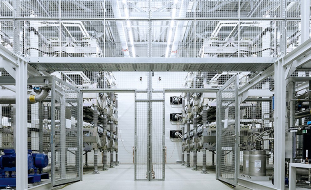
Our Path to the Future
To further optimize our assets and reduce their environmental impact, we are continuously testing alternative gases. We implement these as soon as they are technically mature, thoroughly tested, and operationally reliable. As early as 2018, a pilot project involving 245-kV voltage transformers using synthetic air was put into operation. In addition, current solutions are being developed that will allow parts of 380-kV GIS assets to be insulated with synthetic air over the next few years. In addition to synthetic air, another alternative gas is currently available for GIS in a gas mixture containing the fluorinated insulating gas fluornitrile.
Load Flow Control – Relieving the Load on Power Lines
For several years now, electricity generation from renewable energies has been growing faster than the transmission network. As a result, the transmission network is increasingly reaching its limits. The result is costly interventions in grid operations, known as redispatch. The costs of these interventions are passed on to private households and businesses through grid fees. To ensure that electricity from renewable energies can flow with reliability, Amprion systematically deploys high-performance technologies in the grid, including phase-shifting transformers. With their help, grid operators can control the path that the electricity takes.
What is the operating principle of the Phase Shifting Transformer?
A Phase Shifting Transformer (PST) is operated according to system demand. If, for example, the power flow on a line is too high, grid control engineers reduce the power flow on that specific line by increasing its effective impedance. This is referred to as retard mode. In retard mode, the line is relieved; instead, parallel lines carry a higher share of the power flow. In advance mode, grid control engineers reduce the effective impedance, thereby increasing the power flow on the corresponding line.
What technology is behind this?
In Phase Shifting Transformers — unlike conventional power transformers used for voltage conversion — one winding is connected in series with a circuit. Via the other winding, a quadrature voltage (also referred to as a series injected voltage) is introduced into the circuit. The magnitude and direction of this quadrature voltage influence the effective impedance and thus the power flow of the circuit. Otherwise, the design and physical size of the different transformer types are nearly identical.
How are installation and operation carried out?
Many lines in our transmission network carry two parallel circuits operating at the same voltage level. Wherever we, as the transmission system operator (TSO), need to control power flows, we install two Phase Shifting Transformers accordingly — one per circuit. During the installation of Phase Shifting Transformers, we implement special acoustic mitigation measures, for example through fully enclosed, maximum-attenuation housings.
Playing it safe – Redundancies
Today, we work with innovative technologies and circuit designs, which includes operating assets with multiple busbars: This allows us to create reserves or redundancies and provides us with multiple options for connecting the incoming and outgoing power lines within the asset. This flexibility increases reliability and safety, because in the event of a fault, we can switch to a reserve busbar and route the power via an alternative path.
At the same time, the flexible interconnection allows us to control the flow of electrical energy in the grid within certain limits and to proactively manage individual line sections. Since our switchgear also includes a bypass busbar, we can continue to operate the line without interruption even during maintenance and repair work on the switches.