Substation
Substations are the nodes of our transmission network. They perform various tasks that are crucial to the smooth operation of our grid. Their main tasks include switching power lines on and off and transforming electrical energy from one voltage level to another.

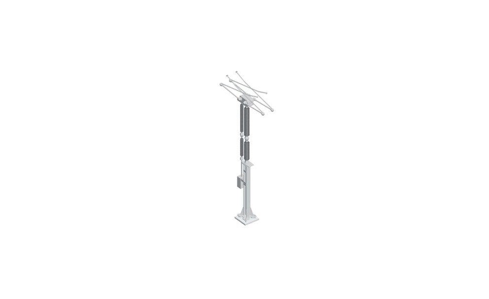
STEPPING VOLTAGE UP OR DOWN – TRANSFORMATION
Our substations connect the transmission network to distribution systems, operating sites of large industrial companies and power plants. To ensure that the power transmission process functions smoothly, the voltage must be adapted to customer requirements. Electrical energy is transformed – from 380 to 110 kilovolts, for example – by powerful transformers.
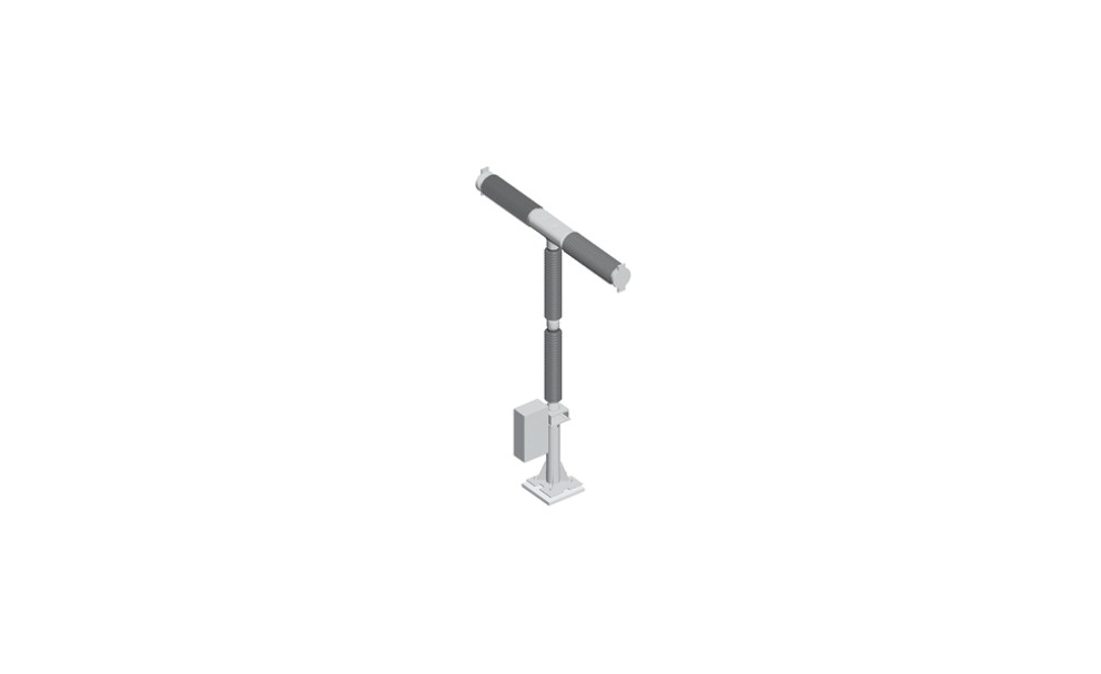
SWITCHING LINES ON OR OFF
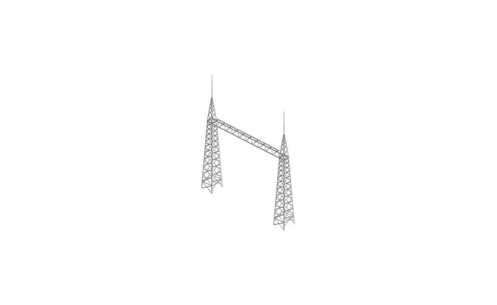
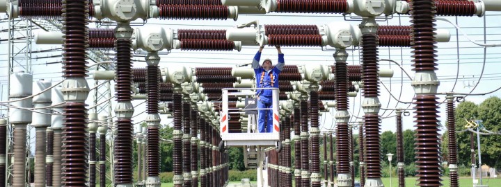
Overhead lines and underground cables converge in our substations and can be switched on or off as required.
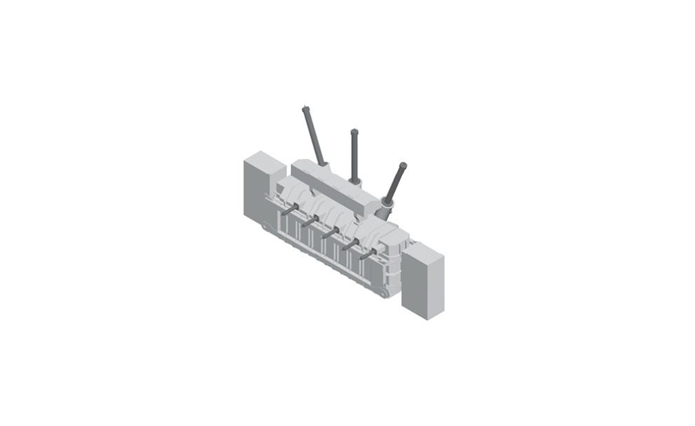
Switching is performed by circuit breakers which ensure safe and reliable de-energising of the electric current during normal operation. In the event of a malfunction, parts of the substation or affected lines are automatically switched off. Our substations are controlled and monitored centrally by our engineers in our network control centres in Rommerskirchen und Hoheneck. They receive measured values from all substations, indicating, for instance, how heavily utilised the individual lines are. Thanks to this data, we can ensure that the electricity reaches its destination without overloading our grid. We also monitor the voltage level and frequency, and make any necessary needs-based adjustments.
PLAYING IT SAFE – REDUNDANCY
Substations have been part of the extra-high voltage network for over 80 years. However, their design and components have been fundamentally optimised over the years. Today, we work with innovative technologies and switching concepts which offer us countless advantages such as operating our substations with multiple busbars. In this way, we have been able to create reserves or redundancies.
This provides us with various options for interconnecting the power lines that enter and leave the substation. This flexibility also results in enhanced reliability and safety for our grid as, in the event of a malfunction, we can rely on back-up busbars and redirect the electricity via an alternative route. A further advantage:thanks to this flexible line circuitry, we are able to control the flow of electrical energy in the grid within certain limits. This helps us to proactively control individual line sections. What’s more, as our substations are equipped with an additional bypass busbar, we are able to keep the line operating without interruption, even when carrying out maintenance or repair work on the switches.
NEW SYSTEMS AND MODERN TECHNOLOGY
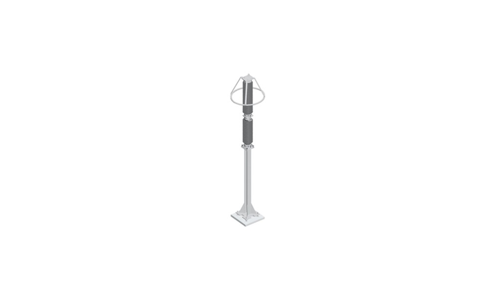
Our substations are increasingly responsible for another important function – they stabilise the voltage level in the grid. During the transmission of AC current, magnetic and electric fields are constantly generated and reversed – a physical characteristic of AC power lines. This requires what is known as “reactive power”. However, this puts a load on the lines in the grid and reduces the useable transmission capacity or the “active power”.
REACTIVE POWER COMPENSATION – STABILISING THE VOLTAGE LEVEL
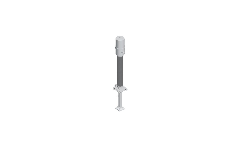
Until now, reactive power has been supplied primarily by the generators of conventional, large power stations. However, as the energy transition progresses, many of these power stations are being removed from the grid. At the same time, the grid’s demand for reactive power is increasing as ever larger power requirements have to be transmitted over long distances. To meet this demand, Amprion is increasingly installing what are known as “reactive power compensation devices” which take over the provision of reactive power. A distinction is made here between static compensation devices (such as reactors or MSCDN systems) and dynamic compensation devices (such as STATCOM or rotating phase shifters). In contrast to their static counterparts, dynamic compensation devices can release or store infinitely adjustable volumes of reactive power, and react very swiftly to changing network conditions.
LOAD FLOW MANAGEMENT – RELIEVING THE LINES
For several years now, the generation of electricity from renewable energies has been growing faster than the transmission network. As a result, the network is increasingly pushed to its limits which leads to costly interventions in grid operations. The costs incurred are passed on to private households and companies in the form of network charges. To ensure the reliable flow of electricity from renewable energies, Amprion systematically uses powerful technologies in the grid, including phase-shifting transformers. With their help, grid operators can control the path taken by the electricity.
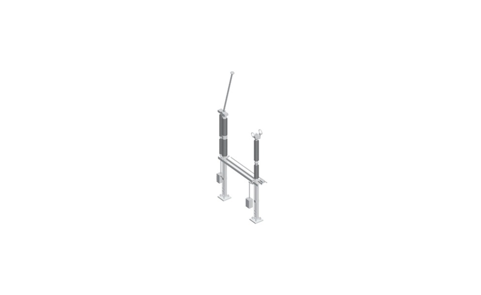
SUBSTATION DESIGN
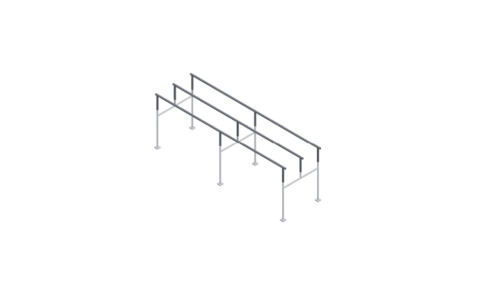
Although different types of substation exist, all Amprion’s substations are designed according to a similar modular principle which ensures their efficient construction and operation. In principle, the switchgear and measuring devices required for each power line circuit and transformer within the substation are arranged in close proximity to one another. This is called the “switchgear bay”. Switchgear bays are interconnected by busbars and couplings. More specifically, a substation is made up of the following main components:
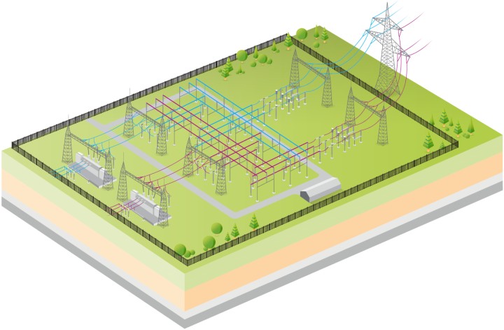
Schematic structure of a transformer substation
The path taken by electricity through a substation
On its path from the incoming power line to the outgoing line, the electricity flows through a series of switchgear, busbars and transformers, which change the voltage level. Each power line circuit has three conductor cables. Consequently, when the electricity reaches the substation, it is fed through three separate switchgears located next to each another.